Brief Summary
This video explains what a rectifier is and how it works to convert alternating current (AC) into direct current (DC). It details the function of PN junction diodes within rectifiers, explaining how they operate in both forward and reverse bias to achieve this conversion. The video covers both half-wave and full-wave rectification processes, highlighting their differences and applications in electronic devices.
- Rectifiers convert AC to DC using PN junction diodes.
- Half-wave rectifiers allow only one half of the AC cycle to pass, while full-wave rectifiers use both halves.
- Rectifiers are used in household electronics and DC charging devices.
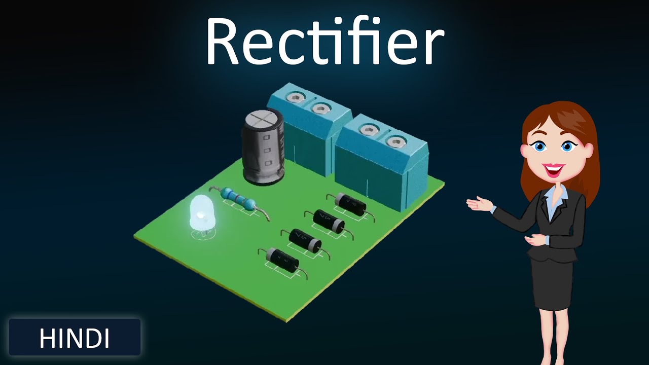
Introduction to Rectifiers
A rectifier is an electronic device that converts alternating current (AC) into direct current (DC). Rectifiers are constructed using PN junction diodes, and their operation is based on the properties of these diodes. The formation of the depletion layer in the PN junction diode plays a crucial role in the rectification process.
PN Junction Diode and Depletion Layer
When a PN junction diode is formed, a depletion layer develops in the absence of an external voltage, creating a potential barrier. In this region, free electrons from the N-side and holes from the P-side combine at the junction. Applying a forward bias to the diode reduces the width of the depletion region, allowing electrons from the N-side to move to the P-side and holes from the P-side to move to the N-side. This movement of majority charge carriers results in current flow, meaning the diode conducts electricity. Conversely, applying a reverse bias increases the depletion region's width, preventing current flow because the diode does not conduct electricity in this state.
Half-Wave Rectification
In a half-wave rectifier circuit, a transformer limits the amount of AC current passing through the diode. When the positive half-cycle of the AC input is applied, the P-side of the diode receives a positive voltage, and the N-side receives a negative voltage, causing the diode to operate in forward bias and conduct current. During the negative half-cycle, the diode operates in reverse bias and does not conduct current. As a result, only the positive half-cycles of the AC input pass through, producing a direct current with only positive half-cycles. This process is called half-wave rectification, and the circuit is known as a half-wave rectifier.
Full-Wave Rectification
To create a full-wave rectifier, a second diode is added to the circuit. When the positive half-cycle of the AC input is applied, diode D1 operates in forward bias while diode D2 operates in reverse bias, resulting in an output from D1. Conversely, when the negative half-cycle is applied, D1 operates in reverse bias and D2 operates in forward bias, producing an output from D2. This arrangement ensures that both halves of the AC cycle are converted into positive half-cycles, providing a more continuous direct current. This process is called full-wave rectification, and the circuit is referred to as a full-wave rectifier.
Applications of Rectifiers
Rectifiers have numerous applications, including use in household electronic devices to convert AC to DC, in DC converters, and in devices that charge with DC power.